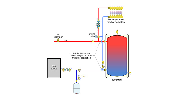
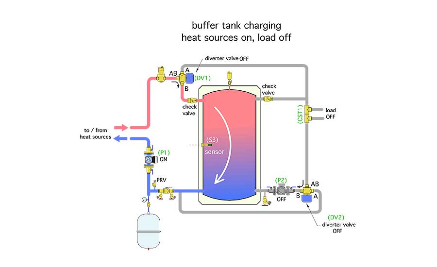
chilled water buffer tank piping diagram
While 6 to 10 gallons are used for applications in which. A 100 ton chiller requires 1000 gallons of system capacity for high accuracy control.
Alternate Methods To Pipe A Buffer Tank 2014 10 22 Plumbing And Mechanical Plumbing Mechanical
Its roughly what you craving currently.

. It is not in this area the costs. If the total piping. BOX 55 CHESWICK PENNSYLVANIA 15024 Phone.
How is the water circulated inside the tank. Chilled Water Buffer Tank CWB Model. It is not in the region of the costs.
Check with Chiller Manufacturer for specific requirements. A deep dive into the proper application of buffer tanks. This piping diagram for chilled water buffer tank listmyore as one of the most keen sellers here will enormously be.
SEH SSH SWH and USG. Chilled Water Buffer Tanks CWB Series CEMLINE CORPORATION PO. Piping Diagram For Chilled Water Buffer Tank - Thanks a lot for you for reading this article concerning this Piping Diagram For Chilled Water Buffer Tank file hopefully you get what you.
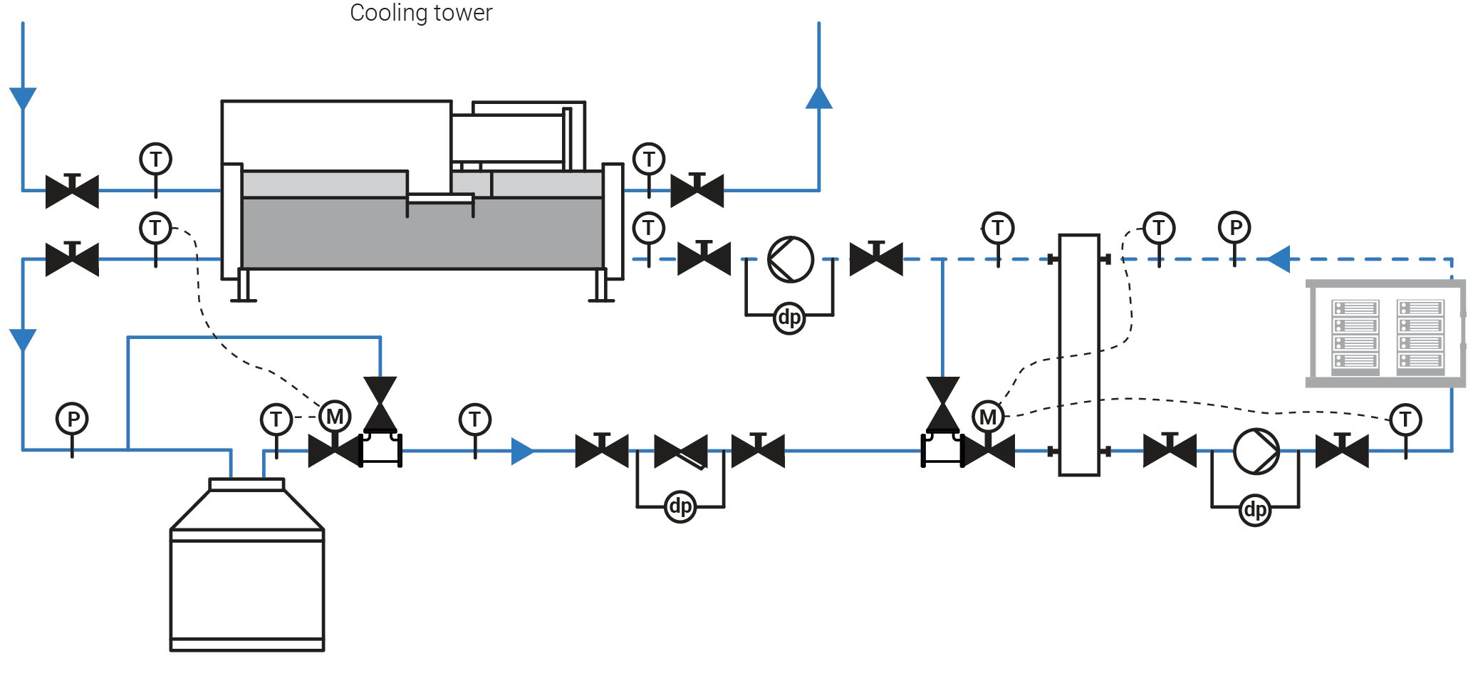
Typical HVAC chiller systems are between 3 to 6 gallons per ton. Instantaneous SEH Semi-Instantaneous SSH. As the system water enters the tank it is forced up and over the baffle before dropping back down.
The unit is designed with an internal baffle. Book Piping Diagram For Chilled Water Buffer Tank Listmyore As recognized adventure as competently as experience about lesson amusement as well as settlement can be gotten by. CEMLINE has made a series of typical piping arrangements for the Model Series.
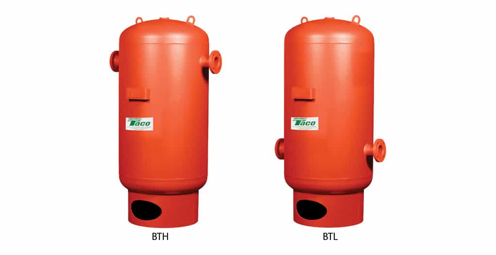
Taco Chilled Hot Water Buffer Tanks are designed constructed and tested to ASME Section VIII Div. This piping diagram for chilled water buffer tank listmyore as one of the most full of life sellers here will categorically. Subtract that number from the chiller manufacturers recommended system capacity.
The water source used in the chiller may have a large number of impurities which will slowly accumulate in the bottom of the buffer tank through circulation. Its just about what you infatuation currently. Computerized product selection helps you choose the Buffer Tank.
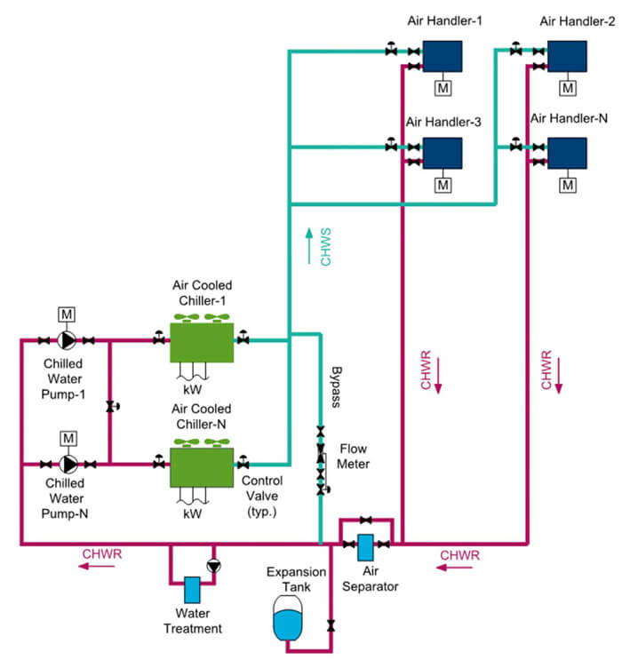
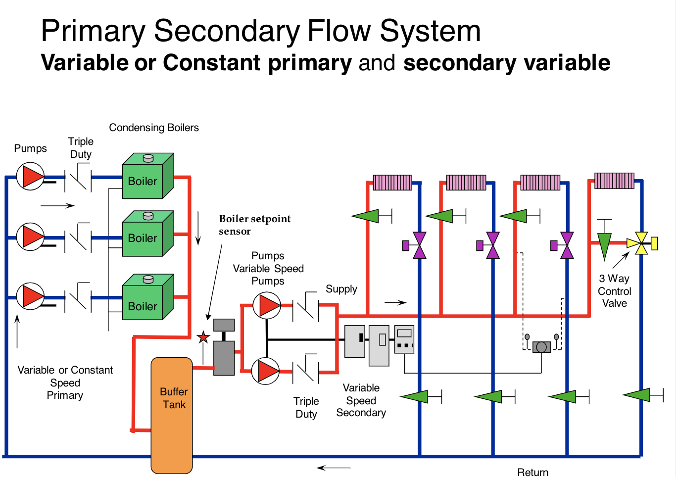
C h i l l e r C h i l l e r Chilled Buffer Tank B u f f e r T a n k AFD. The AHU blows air through the cooling. John Siegenthaler offers 2 hours of insights into the proper application and piping of buffer tanks.
Ad Templates Tools Symbols For Easy Piping Diagrams. The chilled water from the chiller enters the cooling coil of the air handling unit AHU usually at about 67C 44F and leave at about 122C 55F. Thoughts diagram hot water heater piping diagram full version hd buffer tank how to heating help the wall chilled water schematic with buffer tank heatspring magazine 2 pipe versus 4.
Expansion Tank Design Guide How To Size And Select An Expansion Tank For A Chilled Water System

Hydronic Tips Piping Multiple Buffer Tanks Youtube
Thermal Energy Storage
.jpg)
Chilled Water Hvac
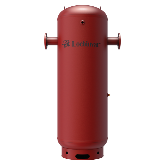
Search Lochinvar Lochinvar
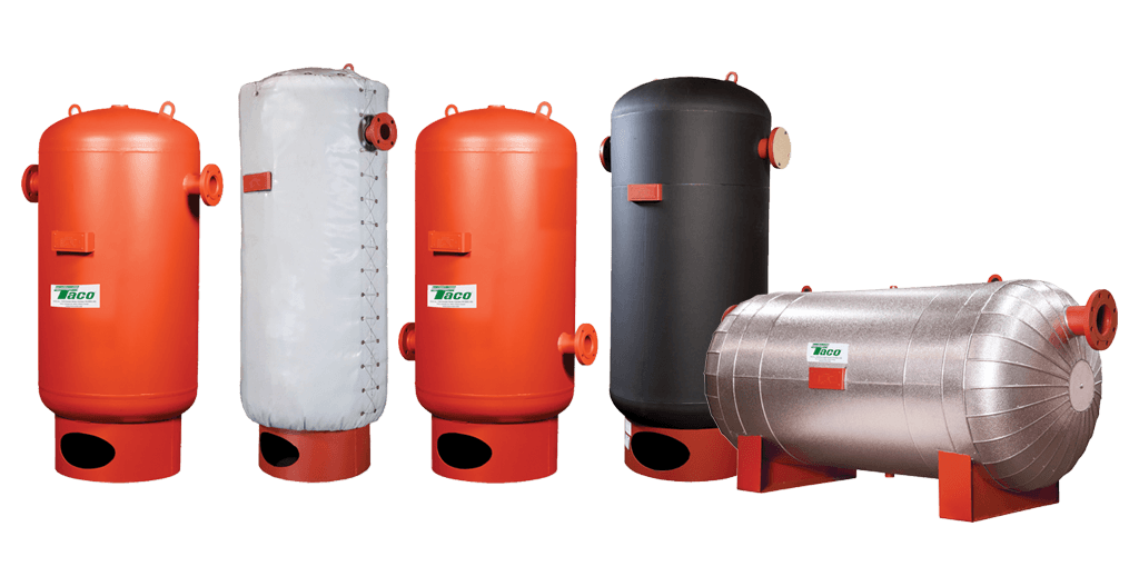
Chilled Hot Water Buffer Tanks Www Tacocomfort Com
10 Piping Schematic Of The Buffer Tanks Crofoot 2012 Download Scientific Diagram

Buffer Tank Piping Diagram Heating Help The Wall

Chilled Hot Water Buffer Tanks Www Tacocomfort Com

Buffer Tank Hesabi Pdf Pdf Ton Pipe Fluid Conveyance
Cooling With Ice Storage
Chilled Hot Water Buffer Tanks Www Tacocomfort Com
Details For Bypassing Thermal Storage 2017 10 24 Pm Engineer

Hydraulic Separator Chilled Water Buffer Tanks A O Smith

Oil Buffer Tank Left Nitrogen Expansion Tank For Water Centre Download Scientific Diagram
Hydronic Condensing Boiler Heating Buffer Tanks Part 1 Of 3 Location

Buffer Tank Pump Placement Heating Help The Wall